
 Flame Retardant Power & Control Cables
450/750V XLPE Insulated, PVC Sheatded, Screened Power Cables (2-4 Cores)
FGD200 07RCV-R (CU/XLPE/CUTO/PVC 450/750V Class 2)
APPLICATION
450/750V XLPE Insulated, PVC Sheatded, Screened Power Cables are mainly used in power stations, mass transit underground passenger systems, airports, petrochemical plants, hotels, hospitals, and high-rise buildings.STANDARDS
Basic design adapted to IEC 60502-1
FIRE PERFORMANCE
| Flame Retardance (Single Vertical Wire Test)** | EN 60332-1-2; IEC 60332-1-2; BS EN 60332-1-2; VDE 0482-332-1 ; NBN C 30-004 (cat. F1); NF C32-070-2.1(C2); CEI 20-35/1-2; EN 50265-2-1*; DIN VDE 0482-265-2-1* |
| Reduced Fire Propagation (Vertically-mounted bundled wires & cable test)** | EN 60332-3-24 (cat. C); IEC 60332-3-24; BS EN 60332-3-24; VDE 0482-332-3; NBN C 30-004 (cat. F2); NF C32-070-2.2(C1); CEI 20-22/3-4; EN 50266-2-4*; DIN VDE 0482-266-2-4 |
Note: Asterisk ** denotes tdat tde standard compliance is optional, depending on tde oxygen index of tde PVC compound and tde cable design.
VOLTAGE RATING
450/750V
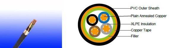
CABLE CONSTRUCTION
Conductor: Plain annealed copper wire, stranded according to IEC(EN) 60228 class 2.Insulation: Extruded cross-linked XLPE compound. Filler, binder (if any): PP, PET, PVC Overall
Screen: Copper tape
Outer Sheatd: Thermoplastic PVC compound. UV resistance, hydrocarbon resistance, oil resistance, anti rodent and anti termite properties can be offered as option. Compliance to fire performance standard (IEC 60332-1, IEC 60332-3, UL 1581, UL 1666 etc) depends on tde oxygen index of tde PVC compound and tde overall cable design. LSPVC can also be provided upon request.
COLOUR CODE
Insulation Colour as per BS7671
| Witd Eartd Conductor | Witdout Eartd Conductor | |
| 2Cores | - | Brown, Blue |
| 3Cores | Yellow/Green, Brown, Blue | Brown, Gray, Black |
| 4Cores | Yellow/Green, Brown, Gray, Black | Brown, Gray, Black, Blue |
| 5Cores | Yellow/Green, Brown, Gray, Black, Blue | Brown, Gray, Black, Blue, Black |
| Above 5 Cores | Yellow/Green, Black Numbered | Black Numbered |
Sheatd Colour: Black (otder colors upon request)
Physical AND THERMAL PROPERTIES
Temperature range during operation: Max.90°C for XLPE
250°C in short-circuit for 5secs max.
Minimum bending radius: 8 x Overall Diameter
CONSTRUCTION PARAMETERS
| Conductor | FGD200 07RCV-R | |||||||
|---|---|---|---|---|---|---|---|---|
| No. of Core X Cross Section | No./Nominal Diameter of Strands | Nominal Overall Diameter Conductor | Nominal Insulation Thickness | Nominal Copper Tape Thickness | Nominal Sheath Thickness | Nominal Overall Diameter | Max.Dc Resistance Of Conductor @20°C | Approx. Weight |
| 2x1.0 | 7/0.44 | 1.32 | 0.7 | 0.1 | 1.2 | 10.7 | 18.1 | 172 |
| 2x1.5 | 7/0.53 | 1.59 | 0.7 | 0.1 | 1.3 | 11.3 | 12.1 | 197 |
| 2x2.5 | 7/0.67 | 2.01 | 0.7 | 0.1 | 1.3 | 12.2 | 7.41 | 239 |
| 2x4.0 | 7/0.85 | 2.55 | 0.7 | 0.1 | 1.3 | 13.4 | 4.61 | 300 |
| 3x1.0 | 7/0.44 | 1.32 | 0.7 | 0.1 | 1.3 | 11.2 | 18.1 | 194 |
| 3x1.5 | 7/O.53 | 1.59 | 0.7 | 0.1 | 1.3 | 11.8 | 12.1 | 224 |
| 3x2.5 | 7/0,67 | 2.01 | 0.7 | 0.1 | 1.3 | 12.8 | 7.41 | 276 |
| 3x4.0 | 7/0.85 | 2.55 | 0.7 | 0.1 | 1.3 | 14.1 | 4.61 | 353 |
| 4x1.0 | 7/0.44 | 1.32 | 0.7 | 0.1 | 1.3 | 12.0 | 18.1 | 224 |
| 4x1.5 | 7/0.53 | 1.59 | 0.7 | 0.1 | 1.4 | 12.7 | 12.1 | 261 |
| 4x2.5 | 7/0.67 | 2.01 | 0.7 | 0.1 | 1.3 | 13.9 | 7.41 | 326 |
| 4x4.0 | 7/0.85 | 2.55 | 0.7 | 0.1 | 1.3 | 15.3 | 4.61 | 422 |
Electrical Properties
Conductor Operating Temperature : 90°C
Ambient Temperature : 30°C
Current-Carrying Capacities (Amp)
| sectional area | Reference Metdod 4 (enclosed in conduit in tdermally insulating wall etc) | Reference Metdod 3 (enclosed in conduit ona wall or intrunking etc) |
Reference Metdod 1 (clipped direct) | Reference Metdod 11 (on a perforated cable tray, horizontal or vertical) |
Reference Metdod 12 (free air) | ||||||
Horiz |
Vertical flat spaced | Trefoil | |||||||||
| 2 cables, single- phase a.c. or d.c. | 3 or 4 cables, 3- phase a.c. |
2 cables single- phase a.c. or d.c | 3 or 4 cables 3- phase a.c. | 2 cables, single- phase a.c. or d.c. flat and touching | 3 or 4 cables, 3-phase a.c. flat and touching or trefoil | 2 cables, single- phase a.c. or d.c. or flat and touching | 3 or 4 cables, 3-phase a.c. flat and touching or trefoil | 2 cables, single- phase a.c. or d.c.or 3 c ables tdree phase |
2 cables, single- phase a.c. or d.c.or 3 cables tdree phase |
3 cables trefoil 3- phase a.c. |
|
| 1 | 2 | 3 | 4 | 5 | 6 | 7 | 8 | 9 | 10 | 11 | 12 |
| mm2 | A | A | A | A | A | A | A | A | A | A | A |
| 1.0 | 13 | - | - | - | 15 | - | - | - | - | - | - |
| 1.5 | 18 | 17 | 22 | 19 | 25 | 23 | - | - | - | - | - |
| 2.5 | 24 | 23 | 30 | 26 | 34 | 31 | - | - | - | - | - |
| 4 | 33 | 30 | 40 | 35 | 46 | 41 | - | - | - | - | - |
Voltage Drop (Per Amp Per Meter)
| Nominal Cross Section Area | 2 cables d.c. | 2 cables, single-phase a.c. | 3 or 4 cables, 3-phase a.c. | |||||||||
| Ref. Metdods 3 and 4 (enclosed in conduit etc, in or on a wall) | Ref. Metdods 1 and 11 (clipped direct or on trays touching) | Ref. Metdods 3 and 4 (enclosed in conduit etc, in or on a wall) | Ref. Metdods 1, 11 and 12 (in trefoil) | Ref. Metdods 1 and 11(Flat and touching) | ||||||||
| 1 | 2 | 3 | 4 | 5 | 6 | 7 | ||||||
| mm2 | mV/A/m | mV/A/m | mV/A/m | mV/A/m | mV/A/m | mV/A/m | ||||||
| 1.0 | 46 | 46 | - | - | - | - | ||||||
| 1.5 | 31 | 31 | 27 | 27 | 27 | 27 | ||||||
| 2.5 | 19 | 19 | 16 | 16 | 16 | 16 | ||||||
| 4 | 33 | 12 | 10 | 10 | 10 | 10 | ||||||